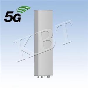
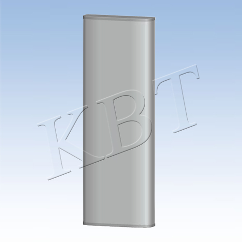
20 ports 2L+8T8R(1721)+8T8R(2327) BF 2.0m Antenna

- KB65D90D0727A20-15D15F16F-I-W
- Base Station Antennas
- 690 – 960/1710 – 2170/2300-2690
- 15/15/16
- 65/90
- ±45°
20 ports 2L+8T8R(1721)+8T8R(2327) BF 2.0m Antenna
F+D Hybrid Serial Antenna
Frequency Range(MHz) | 2*(690 – 960) (R1,R2) | ||
703-803 | 880-960 | ||
Polarization | ±45 | ||
Electrical Downtilt() | 2-12, Independently continuously adjustable | ||
Gain (dBi) | at mid Tilt | 14.8 | 15.4 |
over all Tilts | 14.7±0.6 | 15.3±0.7 | |
Side lobe suppression for first side lobe above main beam (dB) | >15 | >15 | |
Horizontal 3dB Beam Width () | 65±7 | 58±7 | |
Vertical 3dB Beam Width() | 11.5±0.8 | 9.3±0.7 | |
Cross-Polar Ratio , 0°(dB) | >18 | >18 | |
Front to Back Ratio,±30° ( dB) | >21 | >22 | |
| |||
VSWR | ≤ 1.5 | ||
Intermodulation IM3 (dBc) | ≤-150 (2 x 43 dBm carrier) | ||
Cross Polar isolation (dB) | ≥ 25(R1,R2); | ||
Interband isolation (dB) | ≥ 25 | ||
Max. power per port(W) | 250 (R1,R2); | ||
Impedance (Ω) | 50 | ||
Grounding | DC Ground | ||
Values based on NGMN recommendations on Base Station Antenna Standards V12.0(BASTA V12.0) | |||
General Electrical Properties | ||
General parameters | Frequency Range(MHz) | 4*(1710 – 2170)(B1, B2, B3, B4) |
1710-2170 | ||
Polarization | ±45 | |
Electrical Downtilt() | 2-12, continuously adjustbale | |
Electrical downtilt toterance(°) | ±1 | |
Max. power per unit(W) | 50(at 50℃ ambient temperature) | |
Impedance(Ω) | 50 | |
Grounding | DC Ground | |
Calibration and electrical parameters | Coupling factor between calibration port and each antenna port(dB) | -26±2 |
Max. amplitude tolerance from calibration port to input ports(dB) | 0.9 | |
Max. phase tolerance from calibration port to input ports(°) | 8 | |
VSWR | ≤ 1.5 | |
Co-polarization isolation between ports(dB) | ≥ 20 | |
Cross-polarization isolation between ports(dB) | ≥ 23 | |
Electrical Specifications | |||
Radiation parameters | Frequency Range(MHz) | 4*(1710 – 2170)(B1, B2, B3, B4) | |
1710-2170 | |||
Single column beam | Gain(dBi) | 15.0±0.6 | |
Horizontal 3dB Beam Width () | 90±10 | ||
Front to back ratio (dB) | > 25 | ||
Cross-Polar Ratio, 0°(dB) | > 17 | ||
Vertical 3dB Beam Width() | 9.7±0.5 | ||
Side lobe suppression for first side lobe above main beam (dB) | > 16 | ||
NR Broadcast beam | Gain(dBi) | 20.2±0.6 | |
Horizontal 3dB Beam Width () | 65 | ||
Front to back ratio (dB) | > 25 | ||
Vertical 3dB Beam Width() | 9.7±0.6 | ||
Side lobe suppression for first side lobe above main beam (dB) | > 15 | ||
Service beam | Gain(dBi) | 20.2±0.6 | |
Horizontal 3dB Beam Width () | 26 | ||
Front to back ratio (dB) | > 30 | ||
Cross-Polar Ratio, 0°(dB) | > 20 | ||
Beam Isolation (dB) | > 20 | ||
Soft split multi-beam | Gain (dBi) | 19.2±0.6 | |
Horizontal 3dB Beam Width () | 30 | ||
Front to back ratio (dB) | > 30 | ||
Cross-Polar Ratio, 0°(dB) | > 20 | ||
General Electrical Properties | ||
| 2300-2690 (Y1) | |
General parameters | Frequency Range(MHz) | 2300-2690 |
Polarization | ±45 | |
Electrical Downtilt() | 2-12, continuously adjustable | |
Electrical downtilt toterance(°) | ±1 | |
Max. power per unit(W) | 50(at 50℃ ambient temperature) | |
Impedance(Ω) | 50 | |
Grounding | DC Ground | |
Calibration and electrical parameters | Coupling factor between calibration port and each antenna port(dB) | -26±2 |
Max. amplitude tolerance from calibration port to input ports(dB) | 0.9 | |
Max. phase tolerance from calibration port to input ports(°) | 7 | |
VSWR | ≤ 1.5 | |
Co-polarization isolation between ports(dB) | ≥ 20 | |
Cross-polarization isolation between ports(dB) | ≥ 23 | |
TDD LTE Electrical Specifications | |||
Radiation parameters | Frequency Range(MHz) | 2300-2690 | |
Single column beam | Gain(dBi) | 16.0±0.6 | |
Horizontal 3dB Beam Width () | 90±10 | ||
Front to back ratio (dB) | >24 | ||
Cross-Polar Ratio, 0°(dB) | >16.0 | ||
Vertical 3dB Beam Width() | 6.2±0.6 | ||
Side lobe suppression for first side lobe above main beam (dB) | >16 | ||
65° Broadcast beam | Gain(dBi) | 17.2±0.8 | |
Horizontal 3dB Beam Width () | 65±15 | ||
Front to back ratio (dB) | >25 | ||
Vertical 3dB Beam Width() | 6.0±0.6 | ||
Side lobe suppression for first side lobe above main beam (dB) | >15 | ||
Service beam | 0° direct Beam Gain(dBi) | 21.0±0.6 | |
0° direct Beam Horizontal 3dB Beam Width () | 26 | ||
Front to back ratio (dB) | >30 | ||
0° direct Beam Cross-Polar Ratio, 0°(dB) | >18 | ||
Soft split multi-beam | Gain (dBi) | 19.2±0.6 | |
Horizontal 3dB Beam Width () | 30 | ||
Front to back ratio (dB) | > 30 | ||
Cross-Polar Ratio, 0°(dB) | > 20 | ||
Mechanical Specifications | |
RET type | Integrated RET (AISG2.0/3GPP) |
AISG Connectors(2 in 2 out ) | 4x8 pin(in:Male;out:Female) |
Connector | 4x 4.3-10 Female, 2 x (MQ4+MQ5), Bottom |
Passive Antenna dimensions (H x W x D) (mm) | 2100 x 469 x 185 |
Packing dimensions (H x W x D) (mm) | 2400 x 585 x 320 |
Antenna weight (kg) | 38 |
Clamps weight (kg) | 6.8 |
Diameter of installation pole(mm) | φ50-φ125 |
Radome material | Fiberglass |
Radome color | Light grey |
Operational temperature (℃) | -40 to +70 |
Wind load at 42m/s (N) | 1186/461/1186 (Frontal/Lateral/Rearal) |
EOS/EUL | 5 / 10 years |
Max. operational wind speed (km/h) | 200 |