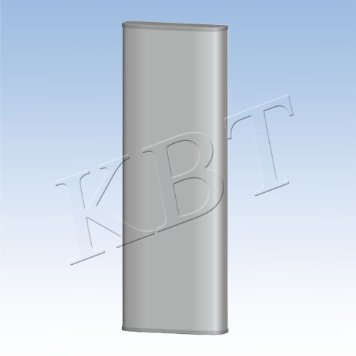
12 ports 2L4H 2.7m Antenna


- KB65D0727C12-17D18F-I-W
- Base Station Antennas
- 690-960/1695–2690
- 17/18
- 65
- ±45°
12 ports 2L4H 2.7m Antenna
FDD Serial Antenna
Electrical Specifications |
| ||||||||
Frequency Range (MHz) | 2 x 690–960 (R1, R2) | ||||||||
690-806 | 806-880 | 880-960 | |||||||
Polarization | ±45° | ||||||||
Electrical Downtilt (°) | 2-12, Independently continuously adjustable | ||||||||
Gain (dBi) | at mid Tilt | 15.6 | 16.2 | 16.6 | |||||
over all Tilts | 15.5±0.7 | 16.1±0.7 | 16.5±0.6 | ||||||
Side lobe suppression for first side lobe above main beam (dB) | >16 | >16 | >16 | ||||||
Horizontal 3dB Beam Width (°) | 63±6 | 60±5 | 56±5 | ||||||
Vertical 3dB Beam Width (°) | 8.4±0.7 | 7.8±0.6 | 7.4±0.5 | ||||||
Cross-Polar Ratio, 0° (dB) | >17 | >17 | >17 | ||||||
Front to Back Ratio, ±30° (dB) | >25 | >25 | >25 | ||||||
Frequency Range (MHz) | 2 x (1695–2690) (Y1,Y3) | ||||||||
1695-1880 | 1850-1990 | 1920-2170 | 2300-2400 | 2490-2690 | |||||
Polarization | ±45° | ||||||||
Electrical Downtilt (°) | 2-12, Independently continuously adjustable | ||||||||
Gain (dBi) | at mid Tilt | 16.6 | 17.2 | 17.4 | 17.8 | 18.2 | |||
over all Tilts | 16.5±0.9 | 17.1±0.7 | 17.3±0.8 | 17.7±0.6 | 18.1±0.8 | ||||
Side lobe suppression for first side lobe above main beam (dB) | >16 | >16 | >16 | >16 | >16 | ||||
Horizontal 3dB Beam Width (°) | 69±9 | 62±5 | 63±6 | 57±5 | 57±6 | ||||
Vertical 3dB Beam Width (°) | 6.8±0.7 | 6.4±0.5 | 6.1±0.6 | 5.4±0.5 | 4.9±0.5 | ||||
Cross-Polar Ratio, 0° (dB) | >16 | >16 | >17 | >18 | >17 | ||||
Front to Back Ratio, ±30° (dB) | >25 | >25 | >25 | >25 | >25 | ||||
Frequency Range (MHz) | 2 x (1695–2690) (Y2,Y4) | ||||||||
1695-1880 | 1850-1990 | 1920-2170 | 2300-2400 | 2490-2690 | |||||
Polarization | ±45° | ||||||||
Electrical Downtilt (°) | 2-12, Independently continuously adjustable | ||||||||
Gain (dBi) | at mid Tilt | 16.2 | 16.8 | 17.0 | 17.3 | 17.8 | |||
over all Tilts | 16.1±0.7 | 16.7±0.8 | 16.9±0.8 | 17.2±0.7 | 17.7±0.9 | ||||
Side lobe suppression for first side lobe above main beam (dB) | >16 | >16 | >16 | >16 | >16 | ||||
Horizontal 3dB Beam Width (°) | 68±8 | 62±5 | 63±5 | 55±5 | 57±9 | ||||
Vertical 3dB Beam Width (°) | 6.8±0.6 | 6.5±0.5 | 6.2±0.6 | 5.4±0.5 | 5.0±0.5 | ||||
Cross-Polar Ratio, 0° (dB) | >16 | >16 | >17 | >16 | >17 | ||||
Front to Back Ratio, ±30° (dB) | >25 | >25 | >25 | >26 | >26 | ||||
VSWR | ≤1.5 | ||||||||
Intermodulation IM3 (dBc) | ≤-153 (2 x 43 dBm carrier) | ||||||||
Cross Polar Isolation (dB) | ≥26 | ||||||||
Interband isolation (dB) | ≥26 (R1, R2), ≥28 (R1, Y1, Y2, Y3, Y4) | ||||||||
Max. power per port (W) | 250 (R1, R2) 200 (Y1, Y2, Y3, Y4) | ||||||||
Impedance (Ω) | 50 | ||||||||
Grounding | DC Grounding | ||||||||
Values based on NGMN recommendations on Base Station Antenna Standards V12.0 (BASTA V12.0) | |||||||||
Mechanical Specifications | |
RET type | Integrated RET (AISG2.0/3GPP) |
AISG Connectors (1 in 1 out) | 2 x 8 pin (in: Male; out: Female) |
Connector | 12 x 4.3-10 Female, Bottom |
Antenna dimensions (H x W x D) (mm) | 2750 x 467 x 167 |
Packing dimensions (H x W x D) (mm) | 2870 x 542 x 292 |
Antenna weight (kg) | 40 |
Clamps weight (kg) | 5.5 |
Diameter of installation pole (mm) | φ50-φ125 |
Radome material | Fiberglass |
Radome color | Light grey |
Operational temperature (℃) | -40 to +65 |
Wind load at 42m/s (N) | 1185/ 525/ 1325 (Frontal/ Lateral/ Rearal) |
Max. operational wind speed (km/h) | 200 |